What is the ESP8266?
The ESP8266 is the Ford model T of the electronics hobbyist: bringing wifi capabilities to the masses at a ridiculously low price. When I first heard about it, it just blew my mind. GPIO + wifi for a couple of bucks?! GET, OUT!
After the initial hype, I quickly realized it was going to be more work than I planned to get the setup I wanted. Indeed, the web is flooded with contradictory information on how to use the chip. There are dozens of ways to use the chip and a seemingly infinite range of devices leveraging it. I had to spend a few days researching how to program and run the damn thing!
That’s why I wrote this guide: This is my personal take on the ESP8266, what I believe is the golden path to ESP8266 development. I will show you the fastest way to get the most value out of this nifty module, based on my experience and on what worked best for me.
If you already know a bit of programming and just want a comfortable and simple environment to write robust IoT applications for cheap, then my friend, you are golden.
Which module should I buy?
Let’s start with the hardware. The ESP8266 chip itself is pretty useless to the hobbyist: It has timy SMD terminals, no antenna, very little memory, no USB interface, and requires a few external resistors even just to boot.
Therefore, when people talk about the EPS8266, they generally mean a board which harnesses the ESP8266 chip. There is a vast ecosystem of such boards and I will describe a handful of those here, including the one I recommend.
ESP-XX modules
These are the most basic and widespread modules for the ESP8266. Orignially built by a company called Ai-Thinker, they feature the bare minimum hardware you’ll need.
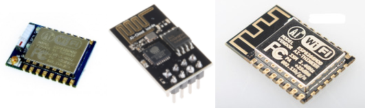
The ESP-01 is the oldest module in this familly. It features 4x2 male pins for power, boot modes, GPIO and UART (note that despite using 2.5mm pins, you cannot plug it in a breadboard since this would short pairs of pins together). You’ll find plenty of tutorials about this module on the web, but they apply to its successors as well. Therefore, there is no significant reason to prefer this module over its successors.
The ESP-12x series is an evolution of the ESP-01, still by the same company. These module fullfill exactly the same role as the ESP-01, but they have a dramatically different interface. The dip male pins are supplanted by 2mm solder pads, which means you can’t plug that in your trusty 2.5mm breadboard. They features an onboard antenna, just like the ESP-01, but are also shielded, which presumably enhances their immunity to RF interference. The most popular nowadays is the ESP-12f which boasts some “improved antenna performance”, whatever that means.
The ESP-07 comes in the same form factor and pinout as the ESP-12f. The major difference we’ll notice as hobbyists is that it doesn’t have an antenna. Instead it features a U.FL socket in which you are supposed to plug an external antenna. This design has a significantly better range while presumably consuming more power (if someone happens to measure that difference, please let me know the results).
Both the ESP-12f and ESP-07 require an additional breakout board to convert the 2mm pins to 2.5mm.
There are more modules in this familly and you can take a look at the list if you are interested. I will not detail how to use them in this article to keep things short. Just know that I advise beginnersagainst using these modules directly. I made the mistake of buying these and lost a few days fixing silly issues that I wouldn’t have faced with a more complete board.
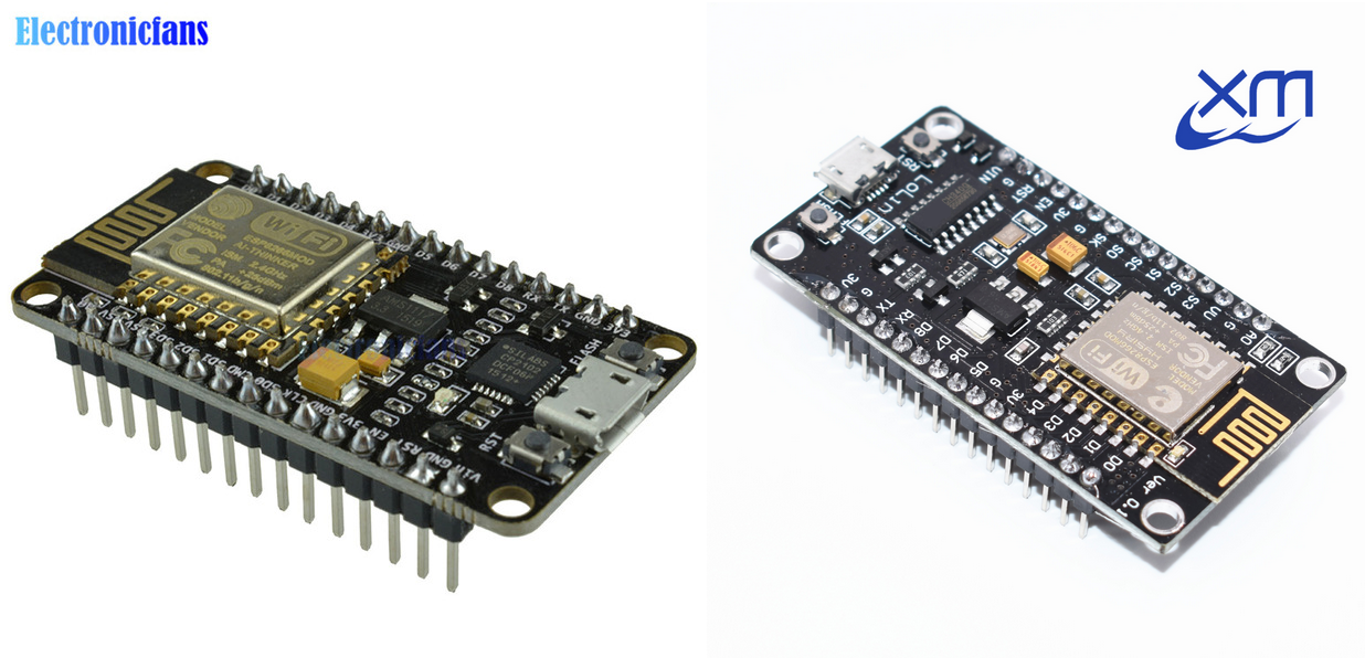
The NodeMCU devkits
The NodeMCU project provides an open source software and hardware solution for working with the ESP8266. Despite being built specifically for the NodeMCU software, the hardware can also be used as a general purpose ESP8266 development kit. We will talk more about the software later.
The original design incorporates an ESP-12E module, a USB-to-UART converter, 5v to 3.3v voltage regulation, a couple push buttons for reset and flash mode, and exports a micro-usb port and 2 rows of 15 DIP male pins. Needless to say it saves a lot of effort working with the chip. Cost-wise it’s between $0.5 and $1 more expensive than a bare ESP-12f. You need all most of the features on the board anyway so don’t try to cut corners and just buy the board already.
At a price tag of just over 3$, this is the only board you’ll ever need for ESP8266-based projects.
By virtue of open source hardware, you will find a lot of variations of the design online and will quickly get lost when shopping. While all boards have similar caracteristics, be aware that some models are impractically large and cover all 10 rows of small breadboards. Therefore, I recommend sticking with the one commonly found under the name “v2” (sometimes also “v1”). See the pictures below to know what to look for. You might also want to take a look at this comparison published by the main contributor to the NodeMCU project.
Note: If you are wondering what NodeMCU has to do with Node.js, well… nothing.
Which software can I use to program the ESP8266?
You should now have a better understanding of the hardware landscape surrounding the ESP8266. Well, that was just the beginning. The software side is even more diverse and confusing than that.
I will teach you the basic principles and show a couple of popular solutions. I will then help you run a proof of concept using the solution that I recommend.
No software
As surprising as it may seem, the ESP8266 is actually first meant to be used as a wifi peripheral, and not to be programmed directly!
The default firmware is a simple serial command interpreter, which means that you can do wifi communication just by sending commands from a terminal (or another microcontroller). For instance, this is how you connect to an access point, and make a GET request to http://httpbin.org/ip:
1 | AT+CIPMUX=0 |
There is plenty of documentation about this interface on the web; therefore, we are going to keep this section short. In this post we are interested in programming the chip rather than using it as a mere peripheral. Why bother adding a $20 arduino in the setup when the ESP8266 alone can handle everything for under $3?!
Low-level C interfaces
This paragraph is key to understanding the diversity of the software ecosystem for the ESP8266, so pay attention.
Espressif systems (the manufacturer of the ESP8266) initially released a software development kit in C that people could use to program the chip. This SDK only had chinese documentation and was rather complex, so for some time the chip remained obscure and unknown of the hacking community. Nowadays, I believe the documentation has been translated to english and the community was able to build powerful frameworks on top of it.
There are two components to this low level SDK: the “RTOS” version and the “SDK” version. A detailed explaination about the differences is way beyond the scope of this article, but just know that developers must chose one and stick with it. One allows you to program inside a real-time operating system (RTOS), the other one hands over complete control to the programmer. Anyways, these details are not super relevant to us. Just know that the tools you’ll use are based on one of these frameworks.
It is very unlikely you’ll ever need to use the low-level C libraries. The frameworks built on top of it are much preferred.
Arduino
Of course it’s a thing! Using the C SDK discussed above, a compatibility layer for arduino was developped. It allows one to program applications on the ESP8266 just like on a regular arduino. No matter how attractive this idea is to you, let me warn you: I do not think it is a good idea to use the Arduino framework to program the ESP8266.
The ESP8266 + arduino combo seems very popular (google around and you’ll see). I think this is mainly due to the authority of Arduino and the fact that many in the Arduino community aren’t programmers, rather than the pure technical characteristics of the solution. Gee, some people love arduino so much they’ll even hook one of those to the ESP8266’s UART for applications that could easily fit on the ESP alone!
The Arduino programming model does not work well with the ESP8266’s architecture.
In arduino, you are usually the sole user of the CPU and you do not care much about power consumption. This allows you to write procedural code in a busy loop, which is easy to understand and is what made arduino so successful to beginners.
On the ESP8266 on the contrary, you share CPU with the networking stack. Monopolize the CPU for too long and the network stack will crash. What’s more, by virtue of being wireless capable, ESP8266 applications are more likely to run off the grid, where battery life is critical; exit the busyloop model!
I salute the effort that has been put in making the ESP8266 as compatible as possible with existing arduino APIs but I think that it is the wrong approach to solving the problem. As we will see next, it is much easier for Arduino enthusiasts to learn a framework tailored for the ESP8266, than it is for the ESP8266 to fit in the Arduino mold.
I am not saying you can’t use the Arduino stack. You can. But in my opinion you will be more productive and save time going directly for the NodeMCU stack.
NodeMCU
This is the way I recommend. NodeMCU is an ambitious idea perfectly put in practice by a group of talented programmers. It solves the problems the arduino-based solution faces while providing an extremely user-friendly environment.
NodeMCU is an open source lua-based operating system for the ESP8266. It contains a lua runtime as well as binary modules to interface with the different hardware capabilities of the EPS8266. It is the best tradeoff between user-friendliness and resource efficiency I am aware of. Its programming model is event-based (the API looks very much like that of Node.js), which makes it particularly efficient and suited for this chip. Despite being based on a scripting language (lua), I found it to run more stable than arduino applications written in C!
Some people might be put off by having to learn lua. The fact is you do not need to know lua in order to use NodeMCU. You will mostly be copy-pasting snippets from the doc, and add a couple functions and if statements. The language is so easy to read and use that you can do basic modifications without any prior knowlege of it. Of course biggger modifications will require a bit of googling, but the time you spend learning lua is time you would spend working around limitations of the other solutions! Trust me, this is the way to go.
Let’s get hacking!
Alright, at this point you should be equipped with a NodeMCU board and be convinced that the NodeMCU software is the way to go. If you have a more guerilla hardware setup, make sure you can talk to the board’s uart at the specified baud rate (115200), and that you drive the boot control pins appropriately (see appendix A).
NodeMCU development is a two step process: First you load a firmware into the chip, then you write your application. Everything happens through the UART port of the chip.
As usual, I provide a complete zip archive containing most of the stuff you’ll need for this tutorial, so you can follow along without interruption. Grab it with this link.
Find your COM port
After you’ve plugged your board to your computer, you will want to find the COM port connected to your ESP8266 chip. One easy way is to go into the arduino IDE, and look at the available options in Tools > Port. Otherwise on OSX, running ls /dev/cu.* will show the list of potential candidates. Just try each of them until you find the right one. Let me the method you use on other platforms so I can add them here.
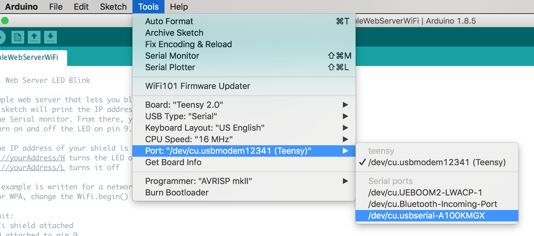
Select one at random, open the serial monitor (the magnifying glass icon on the top right). Make sure you select “115200 baud” and “both NL & CR” in the dropdown at the bottom of the screen. Then depending on what is currently flashed on the board, try either of these two commands: print(node.info()) or else just AT. If the first one returns some numbers, then it means that the chip has already been flashed with a NodeMCU firmware (we are still going to replace it with our own). If the second command works, it means that the chip contains the default firmware by espressif (as discussed in the first section).
If none of them works, try another serial port. It could also be that the chip currently contains garbage and is not able to run anything, or that you booted in “flash mode”. If you are running a bare ESP-XX module, make sure to drive the pins in “boot mode” as shown in appendix A.
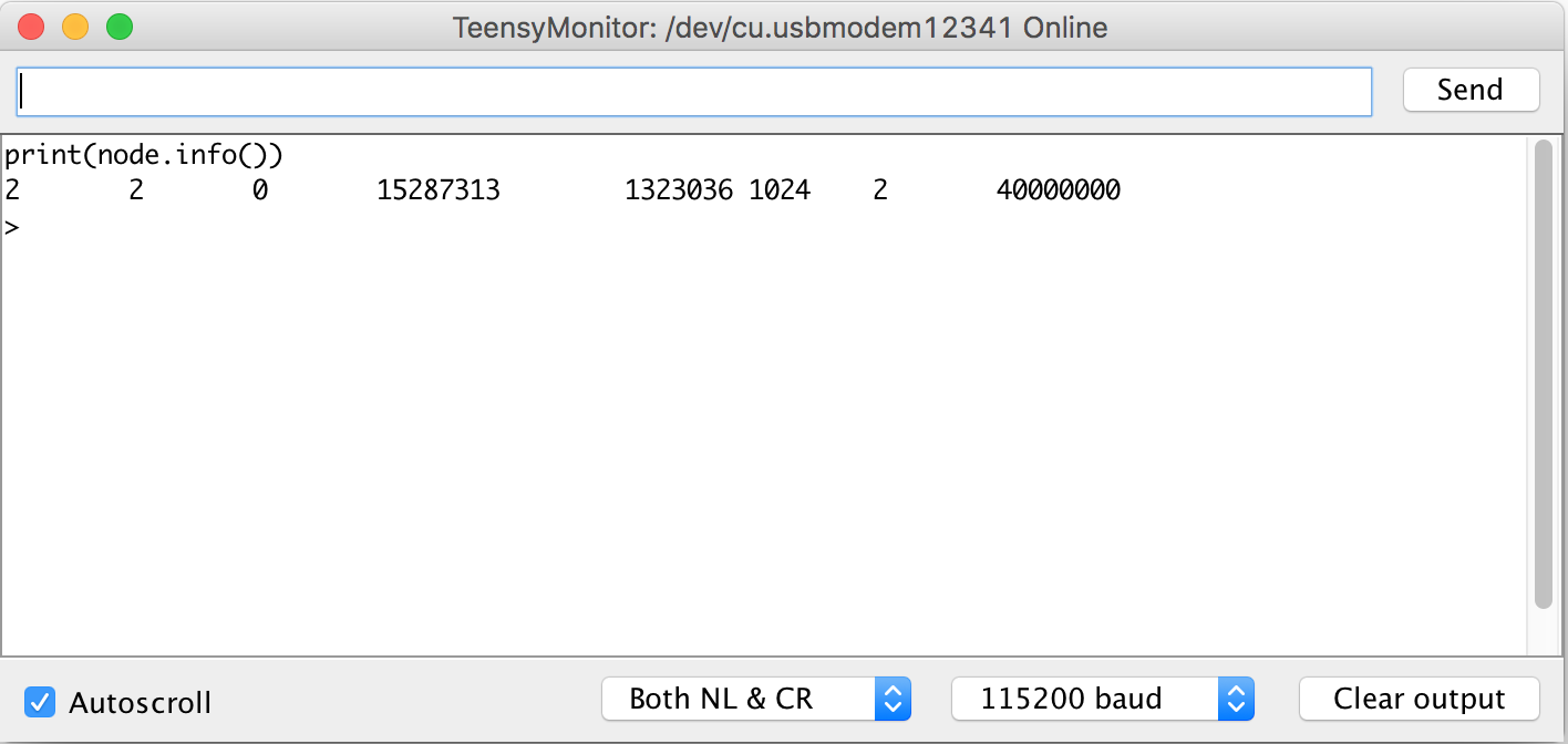
Now that you know which com port talks to the ESP8266, close the serial console, go back to your terminal and save that value to a variable called PORT. For instance, my port is /dev/cu.usbmodem12341 so I type:
1 | export PORT="/dev/cu.usbmodem12341" |
Initial setup
There is one major drawback with NodeMCU: The complete image with all existing modules is too big to fit on the chip! Therefore, you need to select which modules you need for a given application and create a custom image with only these modules.
Fortunately, there are shortcuts:
- First, a cloud build service lets you generate custom images online. Just check the boxes you need, hit “Start your build” and within a few minutes you’ll get your image sent in your mail.
- Alternatively, you can grab a copy of the firmware containing a collection of the most essential modules curated by yours truely. You can download it here.
For this demo, just use the image I provide (second bullet above).
We will flash the image using a handy python script named esptool.py.
All flashing operations happen in “flash” mode. The commands will hang if the board is in “boot” mode. Refer to appendix A to learn more about boot modes.
First, erase the flash memory of the device by running:
1 | python esptool.py --port $PORT erase_flash |
Now, reset your ESP8266 in flash mode again, and proceed to flash the firmware:
(Note that at that point the chip will tend to reboot automatically in “bootloader mode”. It might take some patience to get it to reboot in flash mode. I found that I sometimes need to disconnect the chip from the power source, and hold the “flash” button down while I connect it back to power).
1 | esptool.py --port $PORT write_flash -fm dio 0x00000 nodemcu-essentials-2018-05-02-float.bin |
Tadaa! You can now reboot your board one more time, in “normal” mode. It is ready to use!
Application programming
From now on, we will use a program called nodemcu-uploader to interact with the chip. Install it or just clone the repository somewhere. Test your setup with nodemcu-uploader --version (note: if you cloned the repo, you might need to python /path/to/nodemcu-uploader.py --version instead).
Exploring the interactive prompt
NodeMCU exposes a command prompt on its serial port which you can use to run arbitrary lua code on the chip. nodemcu-uploader actually uses this interface to interact with the chip. Let’s open an interactive terminal with the chip to get a sense of how this works. Make sure you still have the PORT variable around, then run nodemcu-uploader --port $PORT terminal. This should open a terminal connected to your board!
Try the following command:
1 | print('Hello world') |
The device should respond by printing the string ‘Hello world’. Awesome! Now how about we do a little bit of wifi?
Put your chip in station mode with:
1 | wifi.setmode(wifi.STATION) |
Then enter this to get a list of available wifi networks (it takes a few seconds to load).
1 | wifi.sta.getap(1, function (t) |
Now configure the chip to connect to your wifi network with the following command:
1 | wifi.sta.config({ssid = 'YOUR_WIFI_NETWORK_NAME', pwd = 'YOUR_WIFI_PASSWORD'}) |
Wait for a dozen seconds to give it time to connect, and then confirm that you are online using the following command:
1 | print(wifi.sta.getip()) |
If this shows ‘nil’, it means that the NodeMCU did not succesfully connect. Check your wifi password or give it some more time
Now that our piece of awesomness is connected to the internet, let’s make some HTTP requests!
1 | http.get("https://istheinternetdown.com/", nil, function(code, data) |
You should get a response telling you that the internet is not down (hopefully) and return your public IP address.
You can now quit the interactive session. (Note that this terminal’s retarded exit sequence is “CTRL+]”. If you are using a non-US keyboard use CTRL + whatever key is next to the return key)
Uploading a real program
Now that you have a sense of how the NodeMCU terminal interface works, let’s write a real program and upload it to the board.
First, create a file called env.lua. This file will contain your wifi credentials (this is useful to avoid checking secret credentials in source control).
1 | -- env.lua |
Then copy the following program into a file called init.lua
1 | -- init.lua |
Finally, upload both files to the board using nodemcu-uploader:
1 | nodemcu-uploader --port $PORT upload env.lua init.lua |
When you reboot your board, it will look for the file called “init.lua” and run that program. It is useful for debugging purposes to connect to the terminal with nodemcu-uploader --port $PORT terminal while your board is booting. This shows a bunch of info as well as any print statement you put in your code.
Here is what I got:
1 | --- Miniterm on /dev/cu.usbmodem12341 115200,8,N,1 --- |
Now to test your program, take note of the “Station IP” you get and navigate there with your web browser. In my case for instance, I have to navigate to http://192.168.0.22.
Excuse messy breadboard. None of it would have been necessary had I simply bought the NodeMCU devkit. Hopefully I made this mistake so you won’t have to.
This test program lets you control the onboard LED through an HTML interface. Note that I tested this with the ESP-07. It should also work with the ESP-12 as well as any ESP-XX based NodeMCU board where the onboard LED is connected to GPIO2. Other hardware may have the LED connected to a different pin or not have an LED at all.
You are on your own now
That’s it for this tutorial. You now know the basics of the ESP8266 and have a complete development setup that allows you to write any IoT application! Let me give you some additional resources and tips before you leave:
The nodemcu documentation is your ultimate resource to learn all of the NodeMCU APIs. It is extremely powerful and I found it to be generally intuitive to use. That being said, keep in mind that when you run an application on the ESP8266, you are pushing it to its limits. Besides the network stack, it has very limited features and processing power. Even basic HTTP stuff is poorly supported. I advise you use [MQTT](TODO link) instead, a messaging protocol adapted to IoT applications. It is possible to run an HTTP application server on the ESP8266 but that is a complete abuse of the chip and should never be attempted in an application you intend to deploy.
In case you do not want to put all of the pieces together yourself, or if you get stuck somewhere, I provide the “works for me” package: a zip archive containing everything you need to run the experiments shown in this tutorial.
The archive also contains a Makefile which contains helpful tasks for NodeMCU development.
I still can not believe the amount of features that come with the ESP8266 as such a low price tag. The NodeMCU stack is like icing on the cake to me as it makes the programming part of such projects a blast! I feel inspired to build lots of IoT stuff and I hope it you do too.
I invite you to check out the fish feeder I built for my betta. Originally piloted by an arduino, I was able to make it more failure tolerant and enhance its logging capabilities by replacing the arduino with an ESP8266!
And you, what do you want to build with your ESP8266? I’d love to hear your ideas! Feel free to get in touch or share your thoughts in the comment section.
Appendix
Appendix A: Boot mode selection
The following table shows how to select the mode into which the ESP8266 boots. Note that in all cases, GPIO15 must be pulled down and GPIO2 must be pulled high. Some boards, such as the NodeMCU, take care of this for you. Otherwise, use 10k resistors to drive the pins.
| Mode | NodeMCU devkit | ESP-XX or others |
|---|---|---|
| boot | press rst | Pull GPIO0 up with a resistor |
| flash | hold flash and press rst | Bring GPIO0 down |